The "progressive" explanation:
In the simplest coded bitstream, a PCM (Pulse Coded Modulated) digital signal, all samples have an equal number of bits. Bit distribution in a PCM image sequence is therefore not only uniform within a picture, (bits distributed along zero dimensions), but is also uniform across the full sequence of pictures.
Audio coding algorithms such as MPEG-1's Layer I and II are capable of distributing bits over a one dimensional space, spanned by a "frame." In layer II, for example, an audio channel coded at a bitrate of 128 bits/sec and sample rate of 44.1 Khz will have frames (which consist of 1152 subband coefficients each) coded with approximately 334 bits. Some subbands will receive more bits than others.
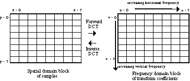
In block-based still image compression methods which employ 2-D transform coding methods, bits are distributed over a 2 dimensional space (horizontal and vertical) within the block. Further, blocks throughout the picture may contain a varying number of bits as a result, for example, of adaptive quantization. For example, background sky may contain an average of only 50 bits per block, whereas complex areas containing flowers or text may contain more than 200 bits per block. In the typical adaptive quantization scheme, more bits are allocated to perceptually more complex areas in the picture. The quantization stepsizes can be selected against an overall picture normalization constant, to achieve a target bit rate for the whole picture. An encoder which generates coded image sequences comprised of independently coded still pictures, such as JPEG Motion video or MPEG Intra picture sequences, will typically generate coded pictures of equal bit size.
MPEG non-intra coding introduces the concept of the distribution of bits across multiple pictures, augmenting the distribution space to 3 dimensions. Bits are now allocated to more complex pictures in the image sequence, normalized by the target bit size of the group of pictures, while at a lower layer, bits within a picture are still distributed according to more complex areas within the picture. Yet in most applications, especially those of the Constant Bitrate class, a restriction is placed in the encoder which guarantees that after a period of time, e.g. 0.25 seconds, the coded bitstream achieves a constant rate (in MPEG, the Video Buffer Verifier regulates the variable-to-constant rate mapping). The mapping of an inherently variable bitrate coded signal to a constant rate allows consistent delivery of the program over a fixed-rate communications channel.
Statistical multiplexing takes the bit distribution model to 4 dimensions: horizontal,
vertical, temporal, and program axis. The 4th dimension is enabled by the practice of
mulitplexing multiple programs (each, for example, with respective video and audio
bitstreams) on a common data carrier. In the Hughes' DSS system, a single data carrier is
modulated with a payload capacity of 23 Mbits/sec, but a typical program will be
transported at average bit rate of 6 Mbit/sec each. In the 4-D model, bits may be
distributed according the relative complexity of each program against the complexities of
the other programs of the common data carrier. For example, a program undergoing a rapid
scene change will be assigned the highest bit allocation priority, whereas the program
with a near-motionless scene will receive the lowest priority, or fewest bits.
Here are some typical statistical conditions addressed by specific syntax and semantic tools:
1. Spatial correlation: transform coding with 8x8 DCT. 
2. Human Visual Response---less acuity for higher spatial frequencies:
lossy scalar quantization of the DCT coefficients. 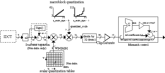
3. Correlation across wide areas of the picture: prediction of the DC coefficient in the 8x8 DCT block.
4. Statistically more likely coded bitstream elements/tokens: variable length coding of macroblock_address_increment, macroblock_type, coded_block_pattern, motion vector prediction error magnitude, DC coefficient prediction error magnitude.
5. Quantized blocks with sparse quantized matrix of DCT coefficients: end_of_block token (variable length symbol).
6. Spatial masking: macroblock quantization scale factor.
7. Local coding adapted to overall picture perception (content dependent coding): macroblock quantization scale factor.
8. Adaptation to local picture characteristics: block based coding, macroblock_type, adaptive quantization.
9. Constant stepsizes in adaptive quantization: new quantization scale factor signaled only by special macroblock_type codes. (adaptive quantization scale not transmitted by default).
10. Temporal redundancy: forward, backwards macroblock_type and motion vectors at macroblock (16x16) granularity.
11. Perceptual coding of macroblock temporal prediction error: adaptive quantization and quantization of DCT transform coefficients (same mechanism as Intra blocks).
12. Low quantized macroblock prediction error: "No prediction error" for the macroblock may be signaled within macroblock_type. This is the macroblock_pattern switch.
13. Finer granularity coding of macroblock prediction error: Each of the blocks within a macroblock may be coded or not coded. Selective on/off coding of each block is achieved with the separate coded_block_pattern variable-length symbol, which is present in the macroblock only of the macroblock_pattern switch has been set.
14. Uniform motion vector fields (smooth optical flow fields): prediction of motion vectors.
15. Occlusion: forwards or backwards temporal prediction in B pictures. Example: an object becomes temporarily obscured by another object within an image sequence. As a result, there may be an area of samples in a previous picture (forward reference/prediction picture) which has similar energy to a macroblock in the current picture (thus it is a good prediction), but no areas within a future picture (backward reference) are similar enough. Therefore only forwards prediction would be selected by macroblock type of the current macroblock. Likewise, a good prediction may only be found in a future picture, but not in the past. In most cases, the object, or correlation area, will be present in both forward and backward references. macroblock_type can select the best of the three combinations.
16. Sub-sample temporal prediction accuracy: bi-linearly interpolated
(filtered) "half-pel" block predictions. Real world motion displacements of
objects (correlation areas) from picture-to-picture do not fall on integer pel boundaries,
but on irrational . Half-pel interpolation attempts to extract the true object to within
one order of approximation, often improving compression efficiency by at least 1 dB.

17. Limited motion activity in P pictures: skipped macroblocks. When the motion vector is zero for both the horizontal and vertical vector components, and no quantized prediction error for the current macroblock is present. Skipped macroblocks are the most desirable element in the bitstream since they consume no bits, except for a slight increase in the bits of the next non-skipped macroblock.
18. Co-planar motion within B pictures: skipped macroblocks. When the motion vector is
the same as the previous macroblock's, and no quantized prediction error for the current
macroblock is present.
Overview of decoding "pipeline": 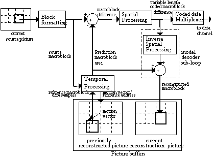
Section D.9 of ISO/IEC 13818-2 is an informative piece of text describing the differences between MPEG-1 and MPEG-2 video syntax. The following is a little more informal.
Sequence layer:
MPEG-2 can represent interlaced or progressive video sequences, whereas MPEG-1 is strictly meant for progressive sequences since the target application was Compact Disc video coded at 1.2 Mbit/sec.
MPEG-2 changed the meaning behind the aspect_ratio_information variable, while significantly reducing the number of defined aspect ratios in the table. In MPEG-2, aspect_ratio_information refers to the overall display aspect ratio (e.g. 4:3, 16:9), whereas in MPEG-2, the ratio refers to the particular pixel. The reduction in the entries of the aspect ratio table also helps interoperability by limiting the number of possible modes to a practical set, much like frame_rate_code limits the number of display frame rates that can be represented.
Optional picture header variables called display_horizontal_size and display_vertical_size can be used to code unusual display sizes.
frame_rate_code in MPEG-2 refers to the intended display
rate, whereas in MPEG-1 it referred to the coded frame rate. In film source video, there
are often 24 coded frames per second. Prior to bitstream coding, a good encoder will
eliminate the redundant 6 frames or 12 fields from a 30 frame/sec video signal which
encapsulates an inherently 24 frame/sec video source. The MPEG decoder or display device
will then repeat frames or fields to recreate or synthesize the 30 frame/sec display rate.
In MPEG-1, the decoder could only infer the intended frame rate, or derive it based on the
Systems layer time stamps. MPEG-2 provides specific picture header variables called repeat_first_field
and top_field_first which explicitly signal which frames or fields are to be
repeated, and how many times. 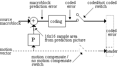
To address the concern of software decoders which may operate at rates lower or different than the common television rates, two new variables in MPEG-2 called frame_rate_extension_d and frame_rate_extension_n can be combined with frame_rate_code to specify a much wider variety of display frame rates. However, in the current set of define profiles and levels, these two variables are not allowed to change the value specified by frame_rate_code. Future extensions or Profiles of MPEG may enable them.
In interlaced sequences, the coded macroblock height (mb_height) of a picture must be a multiple of 32 pixels, while the width, like MPEG-1, is a coded multiple of 16 pixels. A discrepancy between the coded width and height of a picture and the variables horizontal_size and vertical_size, respectively, occurs when either variable is not an integer multiple of macroblocks. All pixels must be coded within macroblocks, since there cannot be such a thing as "fractional" macroblocks.
Never intended for display, these "overhang" pixels or lines exist along the left and bottom edges of the coded picture. The sample values within these trims can be arbitrary, but they can affect the values of samples within the current picture, and especially future coded pictures (since all coded samples are fair game for the prediction process).
To drive this to the point nausea: in the current pictures, pixels which reside within the same 8x8 block as the "overhang" pixels are affect by the ripples of DCT quantization error. In future coded pictures, their energy can propagate anywhere within an image sequence as a result of motion compensated prediction. An encoder should fill in values which are easy to code, and should probably avoid creating motion vectors which would cause the Motion Compensated Prediction stage to extract samples from these areas. To help avoid any confusion, the application should probably select horizontal_size and vertical_size that are already multiples of 16 (or 32 in the vertical case of interlaced sequences).
Group of Pictures:
The concept of the "Group of Pictures" layer does not exist in MPEG-2. It is an optional header useful only for establishing a SMPTE time code base or for indicating that certain B pictures at the beginning of an edited sequence comprise a broken_link. This occurs when the current B picture requires prediction from a forward reference frame (previous in time to the current picture) has been removed from the bitstream by an editing process. In MPEG-1, the Group of Pictures header is mandatory, and must follow a sequence header.
Picture layer:
In MPEG-2, a frame may be coded progressively or interlaced, signaled by the progressive_frame variable. In interlaced frames (progressive_frame==0), frames may then be coded as either a frame picture (picture_structure==frame) or as two separately coded field pictures (picture_structure==top_field or picture_structure==bottom_field).
Progressive frames are a logic choice for video material which originated from film, where all "pixels" are integrated or captured at the same time instant. Most electronic cameras today capture pictures in two separate stages: a top field consisting of all "odd lines" of the picture are nearly captured in the time instant, followed by a bottom field of all "even lines." Frame pictures provide the option of coding each macroblock locally as either field or frame. An encoder may choose field pictures to save memory storage or reduce the end-to-end encoder-decoder delay by one field period.
There is no longer such a thing called "D pictures" in MPEG-2 syntax. However, Main Profile @ Main Level MPEG-2 decoders, for example, are still required to decode "D pictures" at Main Level (e.g. 720x480x30 Hz) [CF NOTE TO SELF: did this change in Singapore?]. The usefulness of D pictures, a concept from the year 1990, had evaporated by the time MPEG-2 solidified in 1993.
repeat_first_field was introduced in MPEG-2 to signal that a field or frame from the current frame is to be repeated for purposes of frame rate conversion (as in the 30 Hz display vs. 24 Hz coded example above). On average in a 24 frame/sec coded sequence, every other coded frame would signal the repeat_first_field flag. Thus the 24 frame/sec (or 48 field/sec) coded sequence would become a 30 frame/sec (60 field/sec) display sequence. This processes has been known for decades as 3:2 Pulldown. Most movies seen on NTSC displays since the advent of television have been displayed this way. Only within the past decade has it become possible to interpolate motion to create 30 truly unique frames from the original 24. Since the repeat_first_field flag is independently determined in every frame structured picture, the actual pattern can be irregular (it doesn't have to be every other frame literally). An irregularity would occur during a scene cut, for example. 3:2 Pulldown Table of Truth
| Prog_seq | prog_frame | pic_struct | top_first | repeat_first | |
| 0 | 0 | Field | 0 | 0 | First coded field displayed first (TB or BT) |
| 0 | 0 | Field | 0 | 1 | Illegal combination |
| 0 | 0 | Field | 1 | 0 | Illegal combination |
| 0 | 0 | Field | 1 | 1 | Illegal combination |
| 0 | 0 | Frame | 0 | 0 | Bottom first, 2 fields displayed (BT) |
| 0 | 0 | Frame | 0 | 1 | Illegal combination |
| 0 | 0 | Frame | 1 | 0 | Top first, 2 fields displayed (TB) |
| 0 | 0 | Frame | 1 | 1 | Illegal combination |
| 0 | 1 | Field | 0 | 0 | Illegal combination |
| 0 | 1 | Field | 0 | 1 | Illegal combination |
| 0 | 1 | Field | 1 | 0 | Illegal combination |
| 0 | 1 | Field | 1 | 1 | Illegal combination |
| 0 | 1 | Frame | 0 | 0 | Bottom first, 2 fields displayed (BT) |
| 0 | 1 | Frame | 0 | 1 | Bottom first, 3 fields displayed (BTB) |
| 0 | 1 | Frame | 1 | 0 | Top first, 2 fields displayed (TB) |
| 0 | 1 | Frame | 1 | 1 | Top first, 3 fields displayed (TBT) |
| 1 | 0 | Field | 0 | 0 | Illegal combination |
| 1 | 0 | Field | 0 | 1 | Illegal combination |
| 1 | 0 | Field | 1 | 0 | Illegal combination |
| 1 | 0 | Field | 1 | 1 | Illegal combination |
| 1 | 0 | Frame | 0 | 0 | Illegal combination |
| 1 | 0 | Frame | 0 | 1 | Illegal combination |
| 1 | 0 | Frame | 1 | 0 | Illegal combination |
| 1 | 0 | Frame | 1 | 1 | Illegal combination |
| 1 | 1 | Field | 0 | 0 | Illegal combination |
| 1 | 1 | Field | 0 | 1 | Illegal combination |
| 1 | 1 | Field | 1 | 0 | Illegal combination |
| 1 | 1 | Field | 1 | 1 | Illegal combination |
| 1 | 1 | Frame | 0 | 0 | 1 prog frame displayed |
| 1 | 1 | Frame | 0 | 1 | 2 progressive frames displayed (illegal in MP@ML) |
| 1 | 1 | Frame | 1 | 0 | Illegal combination |
| 1 | 1 | Frame | 1 | 1 | 3 progressive frames displayed (illegal in MP@ML) |
Slice:
To aid implementations which break the decoding process into parallel operations along horizontal strips within the same picture, MPEG-2 introduced a general semantic mandatory requirement that all macroblock rows must start and end with at least one slice. Since a slice commences with a start code, it can be identified by inexpensively parsing through the bitstream along byte boundaries. Before, an implementation might have had to parse all the variable length tokens between each slice (thereby completing a significant stage of decoding process in advance) in order to know the exact position of each macroblock within the bitstream. In MPEG-1, it was possible to code a picture with only a single slice. Naturally, the mandatory slice per macroblock row restriction also facilitates error recovery.
MPEG-2 also added the concept of the slice_id. This optional 6-bit element signals which picture a particular slice belongs to. In badly mangled bitstreams, the location of the picture headers could become garbled. slice_id allows a decoder to place a slice in the proper location within a sequence. Other elements in the slice header, such as slice_vertical_position, and the macroblock_address_increment of the first macroblock in the slice uniquely identify the exact macroblock position of the slice within the picture. Thus within a window of 64 pictures, a "lost" slice can find its way.
Macroblock:
motion vectors are now always represented along a half-sample grid (NOTE: half-pel has been replaced in nomenclature by the word half-sample to retain consistency with the rest of the MPEG-2 specification). The usefulness of an integer-pel grid (option in MPEG-1) diminished with practice. A intrinsic half-pel accuracy can encourage use by encoders for the significant coding gain which half-pel interpolation offers.
In both MPEG-1 and MPEG-2, the dynamic range of motion vectors is specified on a picture basis. A set of pictures corresponding to a rapid motion scene may need a motion vector range of up to +/- 64 integer pixels. A slower moving interval of pictures may need only a +/- 16 range. Due to the syntax by which motion vectors are signaled in a bitstream, pictures with little motion would suffer unnecessary bit overhead in describing motion vectors in a coordinate system established for a much wider range. MPEG-1's f_code picture header element prescribed a "radius" shared by horizontal and vertical motion vector components alike.
It later became practice in industry to have a greater horizontal search range (motion vector radius) than vertical, since motion tends to be more prominent across the screen than up or down (vertical). Secondly, a decoder has a limited frame buffer size in which to store both the current picture under decoding and the set of pictures (forward, backward) used for prediction (reference) by subsequent pictures. A decoder can write over the pixels of the oldest reference picture as soon as it no longer is needed by subsequent pictures for prediction.
A restricted vertical motion vector range creates a sliding window, which starts at the top of the reference picture and moves down as the macroblocks in the current picture are decoded in raster order. The moment a strip of pixels passes outside this window, they have ended their life in the MPEG decoding loop (that is, if the picture is not needed by future coded pictures as reference). As a result of all this, MPEG-2 created separate into horizontal and vertical range specifiers (f_code[][0] for horizontal, and f_code[][1] for vertical), and placed greater restrictions on the maximum vertical range than on the horizontal range. In Main Level frame pictures, this is range is [-128,+127.5] vertically, and [-1024,+1023.5] horizontally. In field pictures, the vertical range is restricted to [-64,+63.5] since frame structured picture buffers (an implementation design choice) are affected just the same.
Macroblock stuffing is now illegal in MPEG-2. The original intent behind stuffing in MPEG-1 was to provide a means for finer rate control adjustment at the macroblock layer. Since no self-respecting encoder would waste bits on such an element (it does not contribute to the refinement of the reconstructed video signal), and since this unlimited loop of stuffing variable length codes represent a significant headache for hardware implementations which have a fixed window of time in which to parse and decode a macroblock in a pipeline, the element was eliminated in January 1993 from the MPEG-2 syntax. Some feel that macroblock stuffing was beneficial since it permitted macroblocks to be coded along byte boundaries.
A good compromise could have been a limited number of stuffs per macroblock. If stuffing is needed for purposes of rate control, an encoder can pad extra zero bytes before the start code of the next slice. If stuffing is required in the last row of macroblocks of the picture, the picture start code of the next picture can be padded with an arbitrary number of bytes. If the picture happens to be the last in the sequence, the sequence_end_code can be stuffed with zero bytes.
The dct_type flag in both Intra and non-Intra coded macroblocks of frame
structured pictures signals that the reconstructed samples output by the IDCT stage shall
be organized in field or frame order. This flag provides an encoder with a sort of
"poor man's" motion_type by adapting to the interparity (i.e. interfield)
characteristics of the macroblock without signaling a need for motion vectors via the
macroblock_type variable. dct_type plays an essential role in Intra frame pictures by
organizing lines of a common parity together when there is significant interfield motion
within the macroblock. This increases the decorrelation efficiency of the DCT stage. For
non-intra macroblocks, dct_type organizes the 16 lines (... luminance, 8 lines
chrominance) of the macroblock prediction error. In combination with motion_type, the
meaning....
| dct_type | coding mode (macroblock_type / motion_type) | interpretation |
| frame | Intra coded | block data is frame correlated |
| field | Intra coded | block data is more strongly correlated along lines of same parity. |
| Frame | Field predicted |
|
| Field | Field predicted | A typical scenario. A field prediction tends to form a field-correlated prediction error. |
| Frame | Frame predicted | A typical scenario. A frame prediction tends to form a frame-correlated prediction error |
| field | Frame predicted | Makes little sense. If the encoder went through the trouble of finding a field prediction in the first place, why select frame organization for the prediction error? |
Prediction modes now include field, frame, Dual Prime, and 16x8 MC.
The combinations for Main Profile and Simple Profile are shown below. 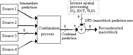
Frame pictures
| motion_type | (transmitted, derived, and total) motion vectors per MB | fundamental prediction block size (after half-sample interpolation) | interpretation |
| Frame | 1, 0, 1 | 16x16 | same as MPEG-1, with possibly different treatment of prediction error via dct_type |
| Field | 2, 0, 2 | 16x8 | Two independently coded predictions are made: one for the 8 lines which correspond to the top field lines in the target macroblock, another for the 8 bottom field lines. |
| Dual Prime | 1, 1, 2 | 16x8 | Two independently coded predictions are made: one for the 8 lines which correspond to the top field, another for the 8 bottom field lines. The opposite parity prediction is formed based on a second vector derived from the first vector coded in the bitstream. |
Field Pictures
| Field | 1, 0, 1 | 16x16 | same as MPEG-1, with possibly different treatment of prediction error via dct_type |
| 16x8 | 2, 0, 1 | 16x8 | Two independently coded predictions are made: one for the 8 lines which correspond to the upper portion of the macroblock, another for the 8 lower lines. The upper and lower halves are not the same as the top and bottom halves of the macroblock in frame coded pictures. |
| Dual Prime | 1, 1, 2 | 16x16 | A single prediction is constructed from the average of two 16x16 predictions taken from fields of opposite parity |
concealment motion vectors can be transmitted in the headers of intra macroblocks to help error recovery. When the macroblock data that the concealment motion vectors are intended for becomes corrupt, these vectors can be used to specify how a concealment 16x16 area is formed from the previous picture. These vectors do not affect the normal decoding process, except for motion vector predictions. At the low level, concealment_motion_vectors are treated like any other motion vector.
Additional chroma_format for 4:2:2 and 4:4:4 pictures. Like MPEG-1, Main
Profile syntax is strictly limited to 4:2:0 format, however, the 4:2:2 format is the basis
of the 4:2:2 Profile (aka "Studio Profile"). In 4:2:2 mode, all syntax
essentially remains the same except where matters of block_count are concerned. A coded_block_pattern
extension was added to handle signaling of the extra two chrominance prediction error
blocks over the old 6 block combination of 4:2:0 chroma_format. The 4:4:4 format is
currently undefined in any Profile, but all the syntax and semantics are included in the
MPEG document to deal with it just the same.
| chroma_format | multiplex order (time) within macroblock | Application |
| 4:2:0 (6 blocks) | YYYYCbCr | main stream television, consumer entertainment. |
| 4:2:2 (8 blocks) | YYYYCbCrCbCr | studio production environments, professional editing equipment, distribution, something to distinguish yourself in marketplace. |
| 4:4:4 (12 blocks) | YYYYCbCrCbCrCbCrCbCr | computer graphics |
Non-linear macroblock quantization was introduced in MPEG-2 to increase the precision of quantization at high bit rates (hence, low quantiser_scale values), while increasing the dynamic range for low bit rate use where larger step size is needed. The quantization_scale_code is switchable between the linear (MPEG-1 style) or non-linear scale on a picture coding (frame or field) basis. This new MPEG-2 non-linear scale corresponds to a dynamic range of 0.5 to 54 with respect to the old linear (MPEG-1 style) range of 1 to 31.
Block:
Block overview diagram: 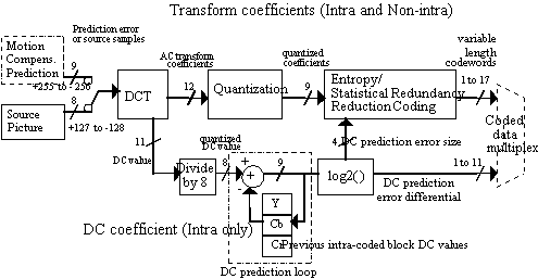
alternate scan introduced a new run-length entropy
scanning pattern generally more efficient for the statistics of interlaced video signals.
Zig-zag scan is considered the appropriate choice for progressive pictures. 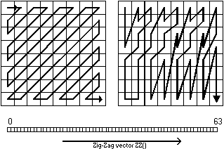
intra_dc_precision: In MPEG-1, it is mandatory that the DC value is quantized to a precision of 8 bits (the DCT expands the dynamic range from 8 bits to 11 bits, so dividing by 8 again, or shifting by 3 bits, brings the value back down to the original range). This is considered bad by some since this single coefficient has more influence on clean video signals than any other. Why not give it more bits ?
So MPEG-2 introduced 9, 10, and 11 bit precision set on a picture basis to increase the accuracy of the DC component. Particularly useful at high bit rates to reduce posterization. Main and Simple Profiles are limited to 8, 9, or 10 bits of precision. The 4:2:2 High Profile, which is geared towards higher bitrate applications (up to 50 Mbits/sec), permits all values (up to 11 bits).
separate quantization matrices for Y and C: luminance (Y) and chrominance (Cb,Cr) share a common intra and non-intra DCT coefficient quantization 8x8 matrix in MPEG-1 and MPEG-2 Main and Simple Profiles. The 4:2:2 Profile permits separate quantization matrices to be downloaded for the luminance and chrominance blocks. Cb and Cr still share a common matrix.
intra_vlc_format: one of two tables may now be selected at the picture layer for variable length codes (VLCs) of AC run-length symbols in Intra blocks. The first table is identical to that specified for MPEG-1 (dc_coef_next). The newer second table is more suited to the statistics of Intra coded blocks, especially in I-frames. The best illustration between Table 0 and Table 1is the length of the symbol which represents End of Block (EOB). In Table zero, EOB is 2 bits. In Table one, it is 4 bits. The implication is that the EOB symbol is 2^-n probable within the block, or from an alternative perspective, there are an average of 3 to 4 non-zero AC coefficients in Non-intra blocks, and 9 to 16 coefficients in Intra blocks. The VLC tree of Table 1 was intended to be a subset of Table 0, to aid hardware implementations. Both tables have 113 VLC entries (or "events").
escape: When no entry in the VLC exists for a AC Run-Level symbol, an escape code can be used to represent the symbol. Since there are only 63 positions within an 8x8 block following the first coefficient, and the dynamic range of the quantized DCT coefficients is [-2047,+2048], there are (63*2047), or 128,961 possible combinations of Run and Level (the sign bit of the Level follows the VLC). Only the 113 most common Run-Level symbols are represented in Table 0 or Table 1. The length of the escape symbol (which is always 6 bits) plus the Run and Level values in MPEG-1 could be 20 or 28 bits in length. The 20 bit escape describes levels in the range [-127,+127]. The 28 bit double escape has a range of [-255, +255]. MPEG-2 increased the span to the full dynamic range of quantized IDCT coefficients, [-2047, +2047] and simplified the escape mechanism with a single representation for this event. The total length of the MPEG-2 escape codeword is 24 bits (6 bit VLC followed by a 6-bit Run value, and 12 bit Level value). It was an assumption by MPEG-1 designers that no quantized DCT coefficient would need greater representation than 10 bits [-255,+255]. Note: MPEG-2 escape mechanism does not permit the value -2048 to be represented.
mismatch control: The arithmetic results of all stages are
defined exactly by the normative MPEG decoding process, with the single exception
of the Inverse Discrete Cosine Transform (IDCT). This stage can be implemented with a wide
variety of IDCT implementations. Some are more suited for software, others for
programmable hardware, and others still for hardwired hardware designs. The IDCT reference
formula in the MPEG specification would, if directly implemented, consume at least 1024
multiply and 1024 addition operations for every block. A wide variety of fast algorithms
exist which can reduce the count to less than 200 multiplies and 500 adds per block by
exploiting the innate symmetry of the cosine basis functions (hardly superstring theory,
but it is regarded so by some).. 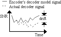
A typical fast IDCT algorithm would be dwarfed by the cost of the other decoder stages combined. Each fast IDCT algorithm has different quantization error statistics (fingerprint), although subtle when the precision of the arithmetic is, for example, at least 16-bits for the transform coefficients and 24-bits for intermediate dot product values.
Therefore, since DCTs are very particular to implementation designs, MPEG cannot standardize a single fast IDCT algorithm. The accuracy can be defined only statistically. The IEEE 1180 recommendation (December 1990) defines the error tolerance between an "ideal" direct-matrix floating point implementation (a direct implementation of the MPEG reference formula) and a test IDCT, such as an integer fast IDCT.
Mismatch control attempts to reduce the drift between different IDCT algorithms by eliminating bit patterns which statistically have the greatest contribution towards mismatches between the variety of methods. The reconstructions of two decoders will begin to diverge over time since their respective IDCT designs will reconstruct occasional, slightly different 8x8 blocks.
MPEG-1's mismatch control method is known canonically as "Oddification," since it forces all quantized DCT coefficients to negative values. It is a slight improvement over its predecessor in H.261. MPEG-2 adopted a different method called, again canonically, "LSB Toggling," further reducing the likelihood of mismatch. Toggling affects only the Least Significant Bit (LSB) of the 63rd AC DCT coefficient (the highest frequency in the DCT matrix). Another significant difference between MPEG-1 and MPEG-2 mismatch control is, in MPEG-1, oddification is performed on the quantized DCT coefficients, whereas in MPEG-2, toggling is performed on the DCT coefficients after inverse quantization. MPEG-1's mismatch control method favors programmable implementation since a block of DCT coefficients when quantized.
Sample:
The two chrominace pictures (Cb, Cr) possess only half the "resolution" in both the horizontal and vertical direction as the luminance picture (Y). This is the definition of the 4:2:0 chroma format. Most television displays require that at least the vertical chrominance "resolution" matches the luminance (4:2:2 chroma format). Computer displays may further still demand that the horizontal "resolution" also be equivalent (4:4:4 chroma format). There are a variety of filtering methods for interpolating the chrominance samples to match the sample density of luminance. However, the official location or center of the lower resolution chrominance sample should influence the filter design (relative taps weights), otherwise the chrominance plane can appear to be "shifted" by a fractional sample in the wrong direction.
The subsampled MPEG-1 chroma position has a center exactly half way between the four nearest neighboring luminance samples. To be consistent with the subsampled chrominance positions of 4:2:2 television signals, MPEG-2 moved the center of the chrominance samples to be co-located horizontally with the luminance samples.
Misc.:
copyright_id extension can identify whether a sequence or subset of frames within the sequence is copyrighted, and provides a unique 64-bit copyright_id_number registered with the ISO/IEC.
Syntax can now signal frame sizes as large as 16383 x 16383. Since MPEG-1 employed a meager 12-bits to describe horizontal_size and vertical_size , the range was limited to 4095x4095. However, MPEG's Levels prescribe important interoperability points for "practical" decoders. Constrained Parameters MPEG-1 and MPEG-2 Low Level limit the sample rate to 352x240x30 Hz. MPEG-2's Main Level defines the limit at 720x480x30 Hz. Of course, this is simply the restriction of the dot product of horizontal_size, vertical_size, and frame_rate. The Level also places separate restrictions on each of the these three variables.
Reflecting the more television oriented manner of MPEG-2, the optional sequence_display_extension() header can specify the chromaticy of the source video signal as it was prior to representation by MPEG syntax. This information includes: whether the original video_format was composite or component, the opto-electronic transfer_characteristics, and RGB->YCbCr matrix_coefficients. The picture_display_extension() provides more localized source composite video characteristics on a frame by frame basis (not field-by-field), with the syntax elements: field_sequence, sub_carrier_phase, and burst_amplitude. This information can be used by the display's post-processing stage to reproduce a more refined display sequence.
Optional "pan & scan" syntax was introduced which tells a decoder on a frame-by-frame basis how to, for example, window a 4:3 image within the wider 16:9 aspect ratio of the coded frame. The vertical pan offset can be specified to within 1/16th pixel accuracy.